Guide to the ePO Conceptual Model
Guide to the ePO Conceptual Model
1. UML diagrams
In this Guide, we describe the UML diagrams that represent the conceptual model of the Ontology.
1.1. Understanding UML
Unified Modelling Language (UML) is a standardised visual language used to describe, specify, design, and document the structure, relationships, and behaviors within a knowledge domain. Although originally designed to model software, It can also be used for business modelling, and for our purposes, Ontology modelling.
1.2. Classes and Attributes:
Figure 1 below depicts a Class in the Ontology.
A class represents a category or a type of entities within a domain. It is a collection of objects that share common
characteristics or properties. A Class can be thought of as blueprint with specifications that an individual
must cover in order to be a member of that Class. Individuals that uphold these specifications.
are called Instances.
Figure 1 represents the class epo:ReviewRequest. The prefix epo specifies the actual ontology that this Class was created from. In this particular case, epo signifies that ReviewRequest is a member of the ePO core module.
Underneath the Class, one can see its Datatype properties, commonly referred to as Attributes. Each Attribute Specifies a constant, which indicates the data type of the value that an object can hold (for example a type of number, a type of text, a representation of time, whether a statement is true or false,etc). Each Attribute also has a prefix, a definition describing it (not seen in the picture), and a cardinality. A cardinality specifies the minimum and maximum number of values that an attribute can have.
For example:
-
Attribute epo:hasNumberOfReviewRequests is a constant of type integer (it can take the value of any integer number).
-
Attribute epo:isWithdrawn is of type boolean (It can only take the values of true or false), and has a cardinality of [0..1] (this attribute can only have a value of 1 or 0).
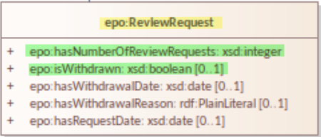
Figure 1: UML visual notation for Class epo:ReviewRequest
1.2.1. Data types
The datatypes that are currently used in EPO (EPO 4.1.0) are the following:
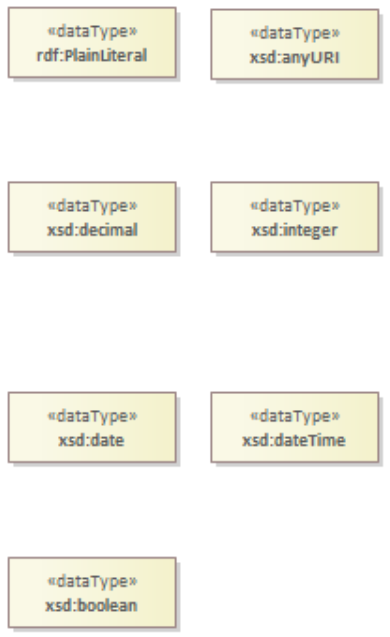
Figure 2: UML visual notation for Datatypes of the Ontology.
-
The prefix XSD (XML Schema Definition) specifies how to describe the elements formally in an Extensible Markup Language document (XML). The ePO makes use of the data types that are shown in Figure 2.
-
Plain Literals represent text and can also include a language tag which indicates the language of that specific text.
-
URI (short for Uniform Resource Identifier) is a character sequence that identifies a logical or physical resource that usually connected to the internet. URLs (web addresses) are the most common URIs.
-
Decimals are numbers that consist of a whole and a fractional part, while integers represent whole numbers.
-
Date is used to represent a certain date, while dateTime is used to represent a certain time point during a day.
-
Boolean is used to represent 2 possible values, usually "true" and "false".
1.3. Associations: Predicates (Object properties), Class generalisations and dependency relationships
There are 3 types of associations between the various concepts of ePO:
-
Predicates (or object Properties) drawn in UML as arrows are used to represent relations between 2 classes. Like attributes, predicates also have cardinalities. For example, Figure 3 depicts predicate epo:playedBy, that connects classes epo:AgentInRole and foaf:Agent. This specific predicate should be read as: "AgentInRole playedBy Agent". Also note that The cardinality of epo:playedBy is 1. This means that each instance of epo:AgentInRole must be played by exactly 1 instance of foaf:Agent.
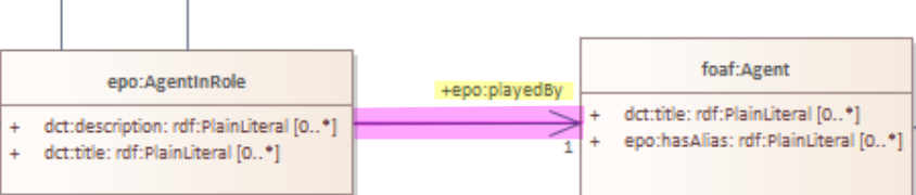
Figure 3: Object Property epo:playedBy
-
Class generalisations / specialisations drawn in UML as arrows with a triangle on top, are similar to the Inheritance concept of object-oriented programming (OOP). Class generalisations are used to define classes that represent similar concepts with other existing classes, with the only difference being a number of extra attributes or predicates. Each class can have many specialisations (incoming arrows) but only one generalisation (outgoing arrow). For example, in Figure 4, org:Organization is a specialisation of foaf:Agent, and foaf:Agent is a generalisation of org:Organization. org:Organization inherits all attributes and predicates of foaf:Agent (such as dct:title), and on top of that, has a number of predicates that are unique to that class, such as attribute epo:hasMainActivityDescription.
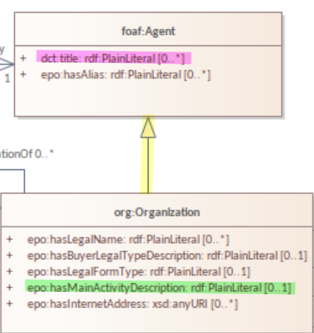
Figure 4: foaf:Agent is the generalisation of org:Organization
-
Predicate generalisations / specialisations drawn in UML similarly to Class generalisations / specialisations, are concepts equivalent to Class generalisations / specialisations, with the difference that they apply to predicates. For example, in Figure 5, predicate epo:isResponsibilityOfBuyer is a specialisation of epo:involvesBuyer. This can be used to represent the idea that a Procedure that is the responsibility of a Buyer should also involve the Buyer in some fashion.
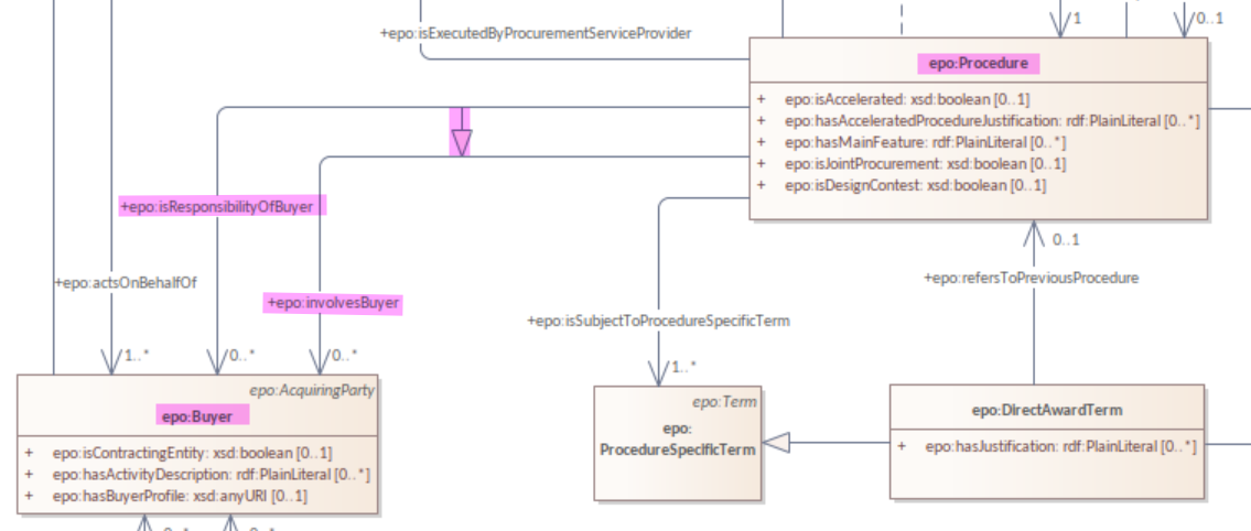
Figure 5: epo:isResponsibilityOfBuyer is a specialisation of epo:involvesBuyer.
-
Dependency relationships, drawn in UML as dashed lines, are predicates that connect a Class with an enumeration. For example, in figure 6, vocabulary at-voc:country is connected to Class person:Person by dependencies epo:hasNationality and epo:hasCountryOfBirth. The distinction between predicates and dependencies exists for 2 reasons:
-
Unlike a class, an enumeration cannot exist alone in an Ontology, but requires a connection to a Class.
-
Enumerations contain vocabularies that exist outside of the Ontology and are not maintained by EPO.
-
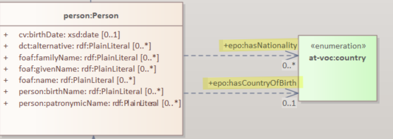
Figure 6: foaf:Agent is the generalisation of org:Organization
1.3.1. Controlled vocabularies
Controlled Vocabularies, also known as taxonomies, are controlled lists of terms used by the ontology. All controlled vocabularies in the ontology, use the prefix at:voc . For example, a Controlled vocabulary could be a list of countries (at:voc:country) or a set of time periods (at-voc:timeperiod).
2. Conceptual model usage (HTML)
-
The conceptual model of the eProcurement Ontology can be found here
-
As of EPO version 4.1.0, The Conceptual model can be viewed either as an HTML page, or in its original form in an Enterprise Architect file (*.EA).
-
As seen in Figure 7, the conceptual model consists of modules, where each module represents a specific part of the procurement process.
-
In this guide, we are going to focus on the main part of the ontology, ePO core .
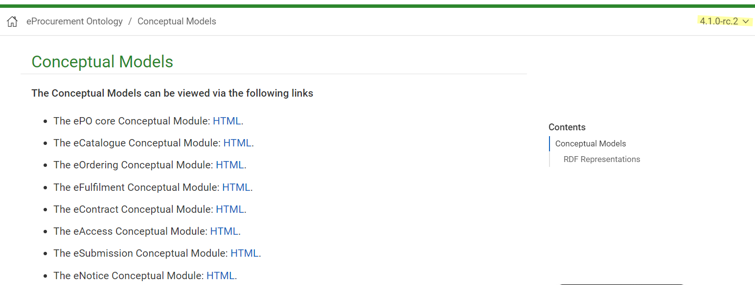
Figure 7: The Conceptual model website. Note the version selector on the top right.
In figure 8, we see the ePO core HTML conceptual model menu .
-
On the right, there is a collection of diagrams that can provide an overview of the Ontology, such as the diagrams for the different procurement phases and diagrams about monetary values.
-
On the left, the file structure of the conceptual model can be browsed. The following files and folders are provided:
-
ePO overview diagram that offers an outline of the ontology.
-
The diagrams folder that contains all diagrams in a hierarchical structure.
-
The classes folder that contains a list of all the classes in the module.
-
The empirical types folder that contains utility classes that the ontology uses as well as a diagram depicting them.
-
The controlled vocabularies folder containing all the vocabularies used in the module.
-
The datatype folder that contains all datatypes that the ontology uses, also described in the [Data types] section of the guide.
-
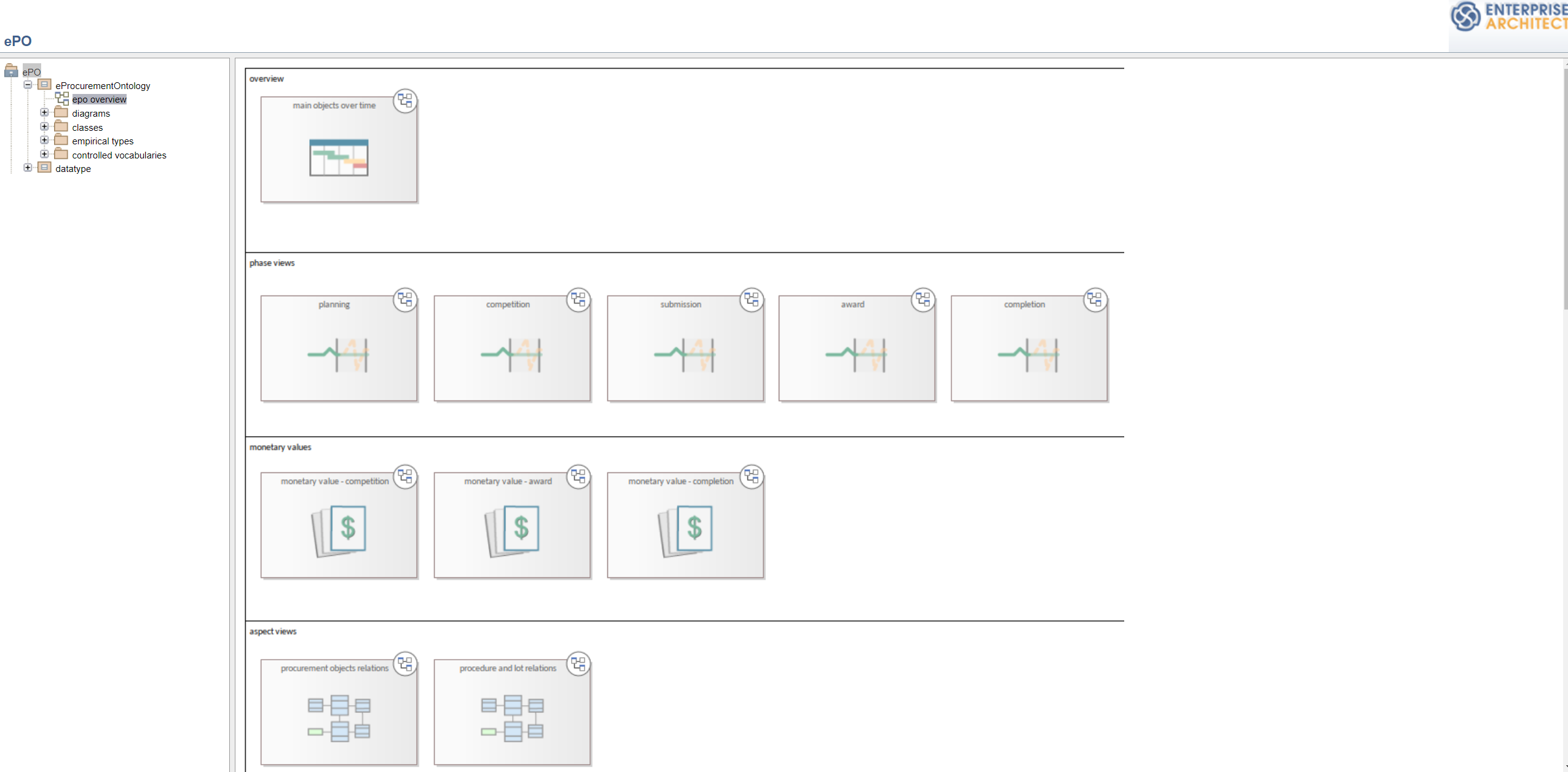
Figure 8: The Conceptual model menu.
2.1. Diagrams of note in ePO core
2.1.1. Μain objects over time and phase oriented diagrams
The Μain objects over time diagram (fig. 9) depicts the most important classes of each procurement phase and their relations. The diagrams under the "phase oriented" directory (fig. 10) offer a more detailed view for each phase.

Figure 9: The Μain objects over time diagram.
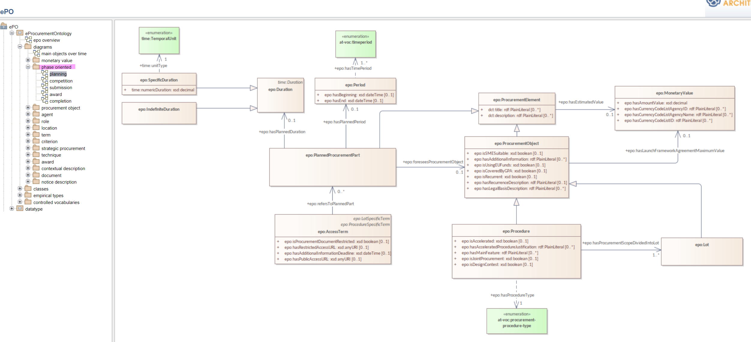
Figure 10: The Planning diagram under the "phase oriented" directory.
2.1.2. Agent hierarchy and agent relations diagrams
As seen in figure 11, An epo:Agent can either be a person (foaf:Person) an organisation (org:Organization) or a system (epo:system). Classes foaf:Person and org:Organization are themselves generalisations of more specific concepts. The prefixes foaf and org signify that these classes were reused from other ontologies and taxonomies by the ePO. Also, on the left of the diagram, we see the directory tree containing the other diagrams of the ontology. Each directory more or less follows the same format. There is one or more key concepts for that directory, "agent", for example, and for each concept there is a hierarchy diagram depicting the hierarchy of the concept, and a relations diagram depicting the concept’s relationship with other classes, or vocabularies.
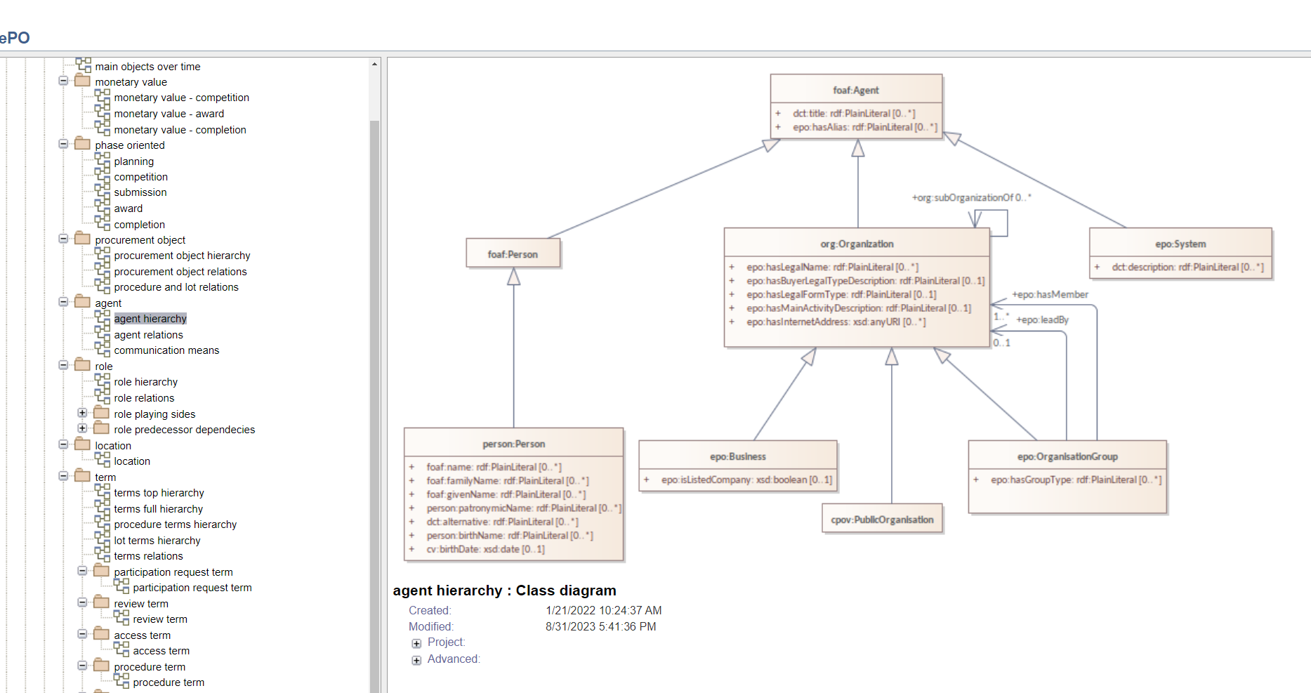
Figure 11: The agent hierarchy diagram
2.2. Browsing Classes on the conceptual model
All classes of a conceptual model are located under the "classes" directory. Figure 11, depicting class cv:Channel offers an example of what a class looks like on the model. As seen on the figure, besides the description of the class, there is a number of tabs where each tab provides information on concepts related to that class. For example, the "Attributes" tab lists all attributes of cv:Channel.
A very useful feature of the conceptual model is that each class lists all diagrams that it appears on. To access that list, press "+" next to the "advanced" indicator under the Class title. For example, we see that in figure 12, there are links for the "role relations", "agent relations", and "communication means" diagrams. There is no link for the Order invoicee diagram, as it is part of the eOrdering conceptual model and not the ePO core model.
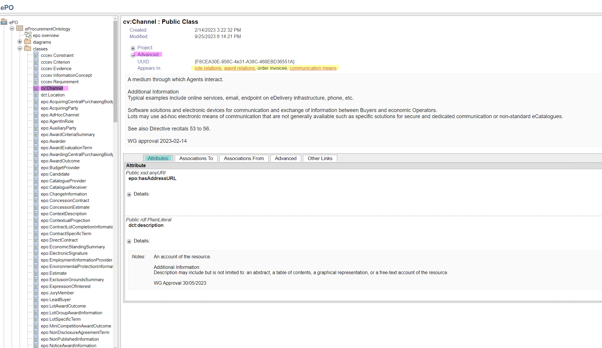
Figure 12 The cv:Channel class on the conceptual model. All diagrams containing it can be found under the "advanced" text.